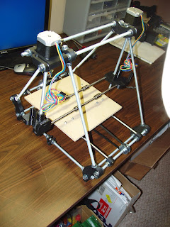
Wednesday, November 27, 2013

Extruder Assembly (Video 14)

Recap: I'm building a Prusa Mendel 3d printer from a kit I purchased from nwreprap.com using a series of videos.

Video 14 was a challenging one to follow.

This video starts out with instructions on attaching the hot end to the extruder using some M3 bolts, but at 4:19 into the video an overlay appears saying: "The latest version of this kit includes an aluminum mounting plate.  You no longer need to use bolts to secure the hotend.  The notches on the top of the hotend slide into the aluminum plate and the plate gets sandwiched between the extruder body and the x carriage.  The bolts were not as effective."

My interpretation: ignore the first 4:19 of this video.  Instead, slide the hot end into the aluminum plate and leave it aside.  It appears that the extruder body + aluminum plate + x carriage "sandwich" will be created in a later video using 2 M4 20mm bolts. 

In this video, we will:
  • prepare the hot end by sliding into aluminum plate
  • prepare the extruder body

Hot end attached to the aluminum plate


Building the Extruder Body

Things you'll need (pics of all parts appear here):

Printed parts: Extruder, idler, small gear, large gear
Metal parts: hobbed bolt and the M8 locknut that comes with it.  Short M8 smooth rod (about 15mm long)
Hardware: 3 bearings, 2 springs, 30 mm M3 bolt, 2 60 mm M3 bolts, 2 M8 washers, 2 M8 nuts, 1 M3 locknut, 7 M3 washers, 4 10mm M3 bolts, 3 M3 nuts

First thing, make sure you clean up the printed parts.  On the extruder, make sure that you drill out the 3 holes for the stepper motor mounting, the hole for the hobbed bolt.  Clean up the slots for the M3 nuts on the extruder and the small gear - I used an Xacto knife for this.  Make sure that the idler fits onto the extruder - I found that a lot of excess material had to be removed.

Prepare the large gear:  put the M8 locknut on the hobbed bolt.  Slide the hobbed bolt through the large gear. 


Large gear with hobbed bolt
Large gear with hobbed bolt showing M8 locknut


Prepare the extruder for installation of the large gear: Install two bearings in the extruder.  Slide the hobbed bolt through the two bearings.  Tighten the M8 locknut until the ridges on the hobbed bolt line up with the center hole on the extruder.  Complete the installation of the large gear by sliding 2 M8 washers into the loose end of the hobbed bolt and tighten with 2 M8 nuts.


Extruder with bearing installed
Extruder showing both bearings


Large wheel and hobbed bolt installed onto the extruder

Adjusting the M8 locknut so that the grooves on the hobbed bolt line up with the hole for the filament

Tightening the hobbed bolt with 2 M8 nuts (on the right)

Prepare the idler: Install a bearing on the short M8 smooth rod and slip into the idler.


Preparing the idler with a bearing and a short M8 rod (1)
Preparing the idler with a bearing and a short M8 rod (2)


Install the idler: Slide the idler onto the extruder.  Attach the idler to the extruder using a 30 mm M3 bolt and an M3 locknut.  Insert the bolt where the large gear is - through the extruder, into the idler, back into the extruder.  If you insert the bolt the other way, the large gear will hit on the M3 locknut.


Idler attached to extruder using 30mm M3 bolt and M3 locknut.  M3 locknut displayed here.


Install the tightening screws: slip two M3 nuts into slots on the idler.  Prepare two 60mm M3 bolts by placing an M3 washer, a spring and another M3 washer on them.  Insert the 60mm M3 bolts through the idler and into the 2 M3 nuts that you slipped into the extruder and tighten until the springs have been compressed to about 20 mm.


Install two M3 nuts (drop them into the two slots)


2 60mm M3 bolts installed and tightened


Attach the stepper motor to the extruder: Using 3 M3 10 mm bolts and 3 washers.  Orient the stepper motor so that the wire point down (see pics).  Do not tighten yet.

Stepper motor attached to extruder

Install the Small gear: drop an M3 nut into a little slot in the small gear. Slide the small gear into the shaft of the stepper motor and insert a 10mm M3 screw into the side of the small gear and screw it in so it catches on the M3 nut. Line up with the screw on the small gear with the flat part of the stepper motor shaft. Tighten the screw.


Prepare the small gear by dropping
a nut into the slot on the side


Small gear has been installed
Position and tighten the stepper motor: Position the stepper motor so that the two gears are flush against each other and one gear cannot move without moving the other. Tighten the 3 M3 bolts that are used to attach the stepper motor.

Important note: I found that the M3 10 mm screw that was holding the small gear in place was hitting the extruder, so the small gear was not rotating freely. I had to shorten the M3 10 mm screw to about 8 mm. I did this using a Dremel tool with a cutting blade.

Last thing: make sure that you rotate the large gear several times around to make sure it rotates smoothly against the small gear. If it sticks, you'll need to remove excess printed material until things turn smoothly. I used an Xacto knife to do this.

Extruder assembly complete (1/4)


Extruder assembly complete (2/4)

Extruder assembly complete (3/4)

Extruder assembly complete (4/4)


Friday, November 22, 2013

Installing the Heat Bed and the Thermistor and Assembling the Hot End (Videos 11, 12 and 13)

There is a helpful page on the NWRepRap site that has hi-res photos of all of the components.

Why do we even need a heat bed?  Why can't we just print directly to a smooth surface at room temperature?  According to this page, printed parts tend to curl as they cool from the bottom up.  So the idea I guess is to keep the entire part warm until it's complete, kind of like a heat lamp is used at a restaurant to keep the entire order warm while it is assembled.

The NWRepRap kit comes with an MK1 heat bed.  Information about the MK1 appears here.  There is also a heat bed called the MK2.  The MK2 is not necessarily "an improved MK1", but the two designs were developed in parallel.  I read somewhere that the MK2 has a hole in the center which makes it easier to level because it is mounted on just 3 points (unlike the MK1 which is mounted on 4 points), but the presence of the center hole results in a cold spot in the center so from that standpoint I have read that the MK1 can be considered superior to the MK2.

You prepare the MK1 heat bed for installation by soldering the 18 gauge wire (mine came in nice red-black pairs) to the heat bed and optionally soldering 2 surface-mount LEDs and a 1 KOhm surface mount resistor.  The LEDs are supposed to light up when current is applied to the heat bed.  Since an LED lights up only when current passes through it in a particular direction, you are advised to mount the two LEDs in opposite directions so that either way you run current through the heat bed, at least one LED will light up.  The surface mount components are tiny and require tweezers to manipulate into place.  If you have any doubt about your soldering abilities, skip this optional step.

There are several options presented in the video for mounting the heat bed on the four M3 screws.  I decided that it would be best to the the springs between the MDF and the heat bed, but to hold the heat bed down, I used M3 locknuts and a washer.  This would make adjusting the height easier than using a dual nut configuration as suggested in the video.

There are two thermistors provided in the NWRepRap kit. They are of the 100k NTC type. One is to be used to measure the temperature of the heat bed and I assume the other will be used to measure the heat of the hot end.

The thermistor for the heat bed is prepared for installation by sliding the PTFE insulator wrapping over the bare leads. Then you place two pieces of skinny heat shrink over the two individual leads and one fatter heat shrink over both stranded wires. Then, you solder the leads to the stranded wires. After the soldering is complete, you heat the skinny heat shrink so it shrinks over the two solder joints and then you slide the fatter heat shrink over the skinny heat shrink and apply heat.

After doing all that it's good to test the resistance of the thermistor at the ends of the stranded wire with a DVM to make sure you don't have a short or an open circuit. Touching your finger to the thermistor should change the resistance.


Testing the resistance of the
thermistor at room temperature
Testing the resistance of the
thermistor at body temperature
Installing the thermistor requires you to physically attach the thermistor to the heat bed or to something heated by the heat bed and to run the thermistor wires to in a similar manner as the heat bed wires.  The video suggests that you kind of push the thermistor up through the hole in the center of the MDF against the bottom of the heat bed and tape the wire with masking tape such that the thermistor stays in contact with the heat bed.  I wasn't so comfortable with this approach because I thought that regular operation would cause vibration that might cause the thermistor to lose physical contact with the heat bed so I researched some alternatives.

I found two suggestions for mounting the thermistor from this blog entry written by Josef Prusa:
  • Attach the thermistor on top of the glass using kapton tape
  • Glue the thermistor on the underside of the heat bed using epoxy
Another opinion is given here (see the post from xiando on Aug 24, 2012):
  • Use kapton tape to attach the thermistor to the underside of the heat bed
  • Small amount of thermal grease between the heat bed and the thermistor encased in some RTV silicone.
I found a product called Arctic Alumina Thermal Adhesive.  Basically it combines the functionality of thermal paste for maximum heat transfer and RTV silicone for adhesion.  NWRepRap advised me to purchase an RTV silicone called Permatex Ultra Copper.  This RTV silicone is to be used in assembling the hot end.

Permatex Ultra Copper comes in a toothpaste tube with a plastic tip that can be attached to it and it's ready to use out of the tube.  Arctic Alumina is epoxy-like and comes in two tubes whose contents must be mixed with a little plastic spatula.


Arctic Alumina and Permatex Ultra Copper

I wanted to compare the thermal conductivity for the Ultra Copper and the Arctic Alumina but neither manufacturers was able to provide thermal conductivity measurements.  However, the technical support person for Arctic Alumina seemed very knowledgeable and explained that for the smallest gaps on the order of the thickness of a piece of paper, Arctic Alumina would perform better with respect to heat conductivity.  It terms of adhesion he claimed that Arctic Alumina would be permanent, while RTV silicone might crack after a while.  So I put my faith in his opinion and went with Arctic Alumina.

I found Arctic Alumina pretty easy to work with.  I mixed it on a piece of Aluminum foil with the provided spatula.  It's a pretty thick paste at that point.  You get about 5 minutes until it transitions from paste to rubber-like semi-solid.  At this point you can use an X-acto knife to scrape any excess.  After about an hour the bond is very strong - I was able to pick up the heat bed by pulling on the wires attached to the thermistor.


Thermistor has been attached to bottom of heat bed using Arctic Alumina 

Heat bed has been mounted.  Heat bed wires are visible on the left and thermistor wires on the right.

The last step in mounting the heat bed is to attach the wires to MDF.  I decided not to drill the two large holes in the MDF as was done in the video and pass the wires through them. The reason is that once you pass the wires through the two holes in the MDF, you have to pull them out through the same holes to remove the heat bed. So instead I drilled two 3mm holes and attached the wires to the MDF with tie wrap. This way, if I ever have to remove the heat bed, I just snip the tie wrap and remove the four lock nuts to free the heat bed.

Heat bed and thermistor wires have been attached to the MDF with two tie wraps

I went on to assemble the hot end.  This requires preparing another thermistor and the heat resistor by soldering wires onto both of them.  Then you attach both of them to the hot end.  Instead of using Permatex Ultra Copper as suggested in the video, I decided to use Arctic Alumina.

Hot end with thermistor and heat resistor installed

Finally I bent the wires and attached them with Kapton tape.

Hot end with heat resistor and thermistor wires neatly attached with Kapton tape.

This is how my Prusa Mendel looks at the end of video 13.


Friday, November 8, 2013

Z Axis (Video 10)

At 1:00 in the video, it's not clear from the video whether the X axis threaded rod goes above or below the Y axis threaded rods.  It goes below like this:


Then, the suggested order of items on the X axis threaded rod is:

  • M8 Nut
  • M8 washer
  • printed bar clamp (pass through holes)
  • M8 washer
  • M8 Nut
  • printed bar clamp (pass through apex)
  • [ large space .... ]
  • printed bar clamp (pass through apex)
  • M8 nut
  • M8 washer
  • printed bar clamp (pass through holes),
  • M8 washer
  • M8 Nut

I started to measure out all of the distances to ensure that the rods all line up.  This was tedious and error-prone.  Since I didn't have the printed bar clamps that sit on the Y axis threaded rods tightened yet, the X axis threaded rods were free to move along both the X and the Y axis.  This made things really difficult.  So I decided to take the X axis threaded rod out and add two pairs of M8 nuts to hold the threaded rod in place along the X axis.  My order of items on the X axis threaded rod (with my additions in red is:


  • M8 Nut
  • M8 washer
  • printed bar clamp (pass through holes)
  • M8 washer
  • M8 Nut
  • M8 Nut
  • M8 washer
  • printed bar clamp (pass through apex)
  • M8 washer
  • M8 Nut
  • [ large space .... ]
  • M8 Nut
  • M8 washer
  • printed bar clamp (pass through apex)
  • M8 washer
  • M8 Nut
  • M8 nut
  • M8 washer
  • printed bar clamp (pass through holes),
  • M8 washer
  • M8 Nut


  • M8 nuts and washers I added to make it easier to line up the X axis threaded rod


    Making sure that the Z axis smooth rods are parallel and plumb is especially difficult.  I found that it was possible to position my ruler in these two ways to make the necessary measurements.  My rules is an Empire 18" Stainless Steel Rule Model 27318.


    For the measurement at the top of the smooth rods


    For the measurements near the bottom of the smooth rods

    I was about to attach the linear bearings on the Z axis smooth rods to the X ends using zip ties.  The left linear bearing lined up well with the left X end, but I discovered that there was a 1/4" gap between the right linear bearing and the right X end.  So I had to measure the distance between the Z lead screws at the top and adjust the distance between the X ends to so that the Z lead screws are parallel.  It was hard to do this accurately because the X ends do not slide easily along the X axis smooth rods.

    This is what my Prusa Mendel looks like after I attached the linear bearings on the X ends using zip ties:


    Wednesday, November 6, 2013

    Mounting the Z motors and X axis smooth rods (Video 9)

    In the beginning of Video #9, the Prusa Mendel being assembled in the video has a small issue with the Y axis belt binding because it's not centered.  This is the same issue I experienced during the installation of the Y axis belt in Video 8. The take-away from this issue is to carefully center the clamps that hold the Y smooth rods as described in the blog entry for videos 5 and 6.

    A small issue - I had to drill out the X ends with a 5/16" drill bit.  Don't forget to put the linear bearings on the smooth rods before putting the X ends on!

    The main issue I experienced during this step was attaching the Z axis motor to the lead screw using the couplings.  This occurred at 5:40 in the video.  The couplings that were included in my kit were not the same as in the video and they didn't actually work.  The couplings described in the video were made of aluminum and had 4 grub screws that tightened against the motor shaft and lead screw.  My coupling were made of aluminum and had just two screws that simply tightened the coupling around the motor shaft and lead screw kind of like a belt around a waist. More importantly, once the screws were fully tightened, the coupling was still loose on the lead screw so it wasn't functioning properly.

    I called the NWRepRap help line and Aaron Dale answered.  He explained that if I wanted to use the aluminum coupling from the kit, I would have to insert a spacer such as a couple layers of electrical tape or shrink wrap to close the gap.  Alternatively I had the option of using printed plastic couplings that were also in my kit.  The plastic couplings come in the form of two shells that clamp around the motor shaft and lead screw using 4 14mm M3 screws.  I didn't like either option very much, so Aaron kindly offered to mail me a set of aluminum couplings just like in the video.  They arrived a few days later via first class USPS and worked very well.

    Aaron explained that the consensus in the RepRap community is that the plastic couplings are better because the aluminum couplings stretch out over time.  While that may be true, I examined the plastic couplings and I suspect that the amount of tension required to get a tight grip would probably put great stress on these pieces.  If they aren't tight enough, then the Z axis lead screw will slip with respect to the Z motor.

    Here is how the plastic couplings look and fit:


    Here is how the aluminum couplings that are shown in the video look and fit:

     
    Here is how my Prusa looks after Video 9 with the Z motors  and X axis is installed:


    Installing The Y Axis Belt and Stepper Motor (Video 8)

    One of the problems I noticed is that the entire bed was not centered so that the belt did not cover the center of the bearings.  The entire bed had to be moved 2 mm by adjusting the position of the Y clamps which subsequently moved the Y axis smooth rods. 

    Other than that, the installation of the Y axis belt and stepper motor is pretty straighforward as described in the video.

    Friday, November 1, 2013

    Installing The MDF Bed (Video 7)

    I started following directions for installing the MDF Bed in Video 7 which is a 24 minute video.

    Things were progressing very smoothly until about 10 minutes into the video.  First, the video informed me that the MDF bed bearing mounts clip on to the bearings.  Right then, a text overlay popped up over the center of the video and informed me that this type began failing after the video was made.  So at some point in time, NWRepRap started shipping a different type of MDF bed bearing mount that is to be secured with zip ties.  You can click on the little X on the upper right of the overlay to close it so you can see the video underneath.

    I didn't immediately see how this was possible, so I went to NWRepRap's web site and requested help.  About 15 minutes later, I got a helpful email with some pics.  The pics showed me slots where the zip ties fit.  Here they are (courtesy of Aaron Dale at NWRepRap):


    Around 11:30 into the video, Aaron does a pretty impressive contortion/balancing act.  He places the unattached MDF bed on top of the bearing mounts which are clipped into the bearings.  Then he manages to look underneath the MDF bed (which is only about 4 inches off the table top) and mark eight holes on the underside of the MDF bed with a pencil.

    The bed bearing mounts  that came with my kit are not clip-on.  They simply lay on top of the bearing until I secure it with a zip tie.  The slightest push and they simply slide off the bearing and fall onto the table underneath.  So I did not even attempt Aaron's acrobatic feat.  Instead I carefully measured out the position of the holes with a ruler and digital caliper based on the size of the bearing mounts and the distance between the Y axis smooth rods.  Here is a pic of my MDF bed before mounting:


    Here is what my kit looks like after Video 7: