Recap: I've built a Prusa Mendel 3-D printer from a kit I purchased from nwreprap.com. I am performing
some calibration steps before I attempt the first print.
One of the things we haven't done yet is determine the final position of the Z limit switch and adjust the height of the heat bed at each corner.
In order to complete this step, you must have
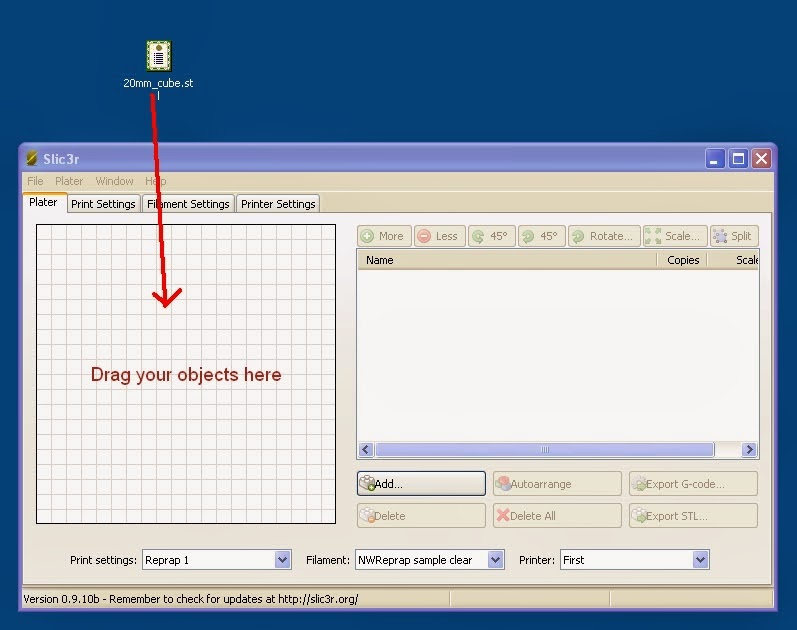
downloaded the software,
installed the Arduino drivers ,
uploaded the firmware and you must be able to
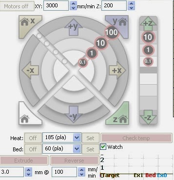
operate Pronterface. You'll also need a couple pieces of regular white paper - the kind that goes into a laser or inkjet printer and a good quality ruler.
Before you get started with the calibration, an initial check to ensure that your piece of glass is flat is advised.
Detecting a Warped Piece of Glass Before Installation
Lay the glass on a flat surface. Tear off a piece of paper. Lay the edge of the ruler on the glass. Now try to wedge the piece of paper between the ruler and the glass at the edges of the glass and in the center. If there is space between the ruler and the glass, then paper will fit between the ruler and the glass. This means that either the glass or the edge of the ruler is warped. Try using flipping the ruler and using the other edge of the ruler. If the results are the same, then the glass is likely warped. If the first test succeeds, turn the glass 90 degrees and repeat it in the other direction.
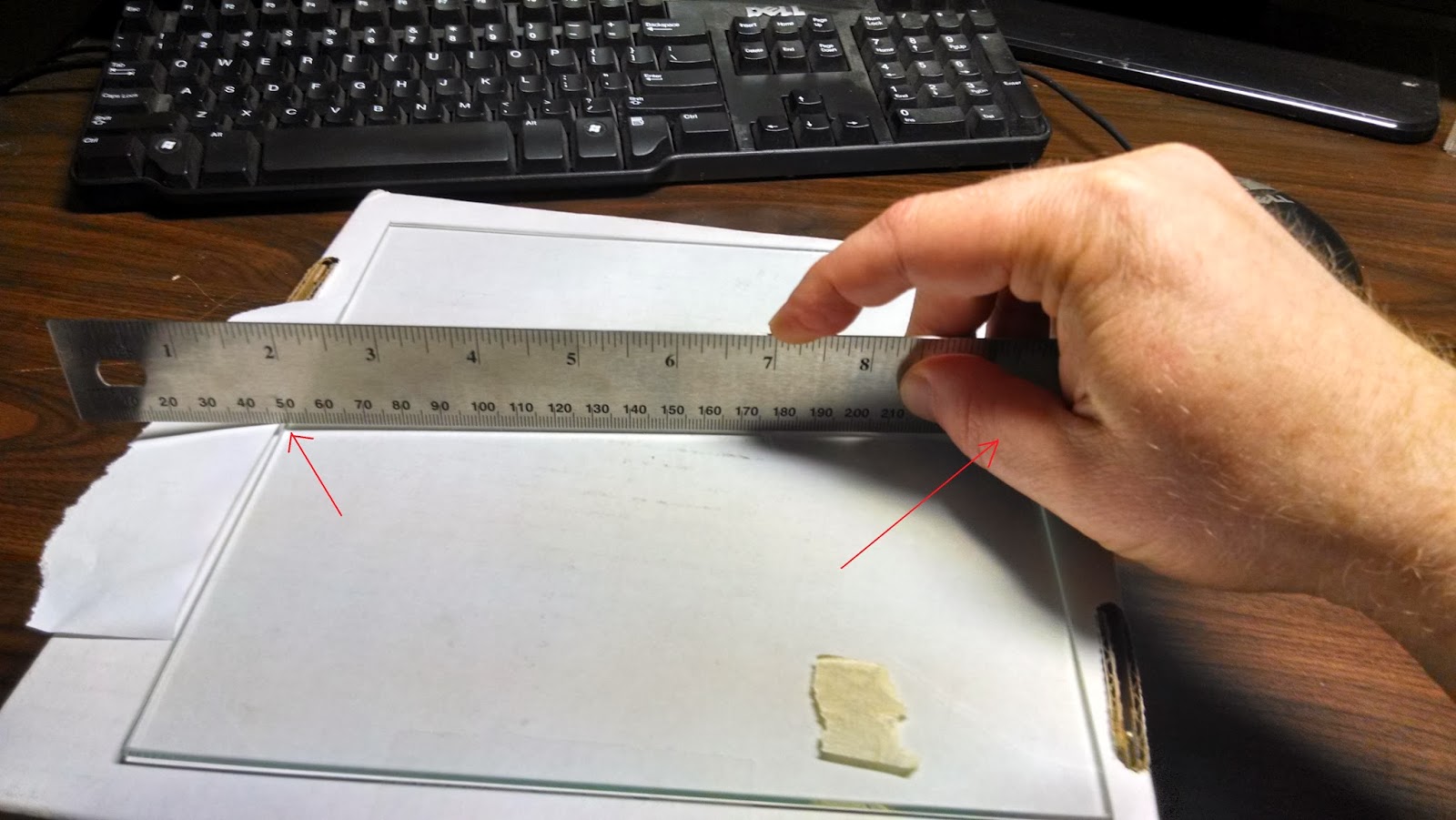 |
Test for warped glass by sliding a scrap of paper between the ruler and edge of glass
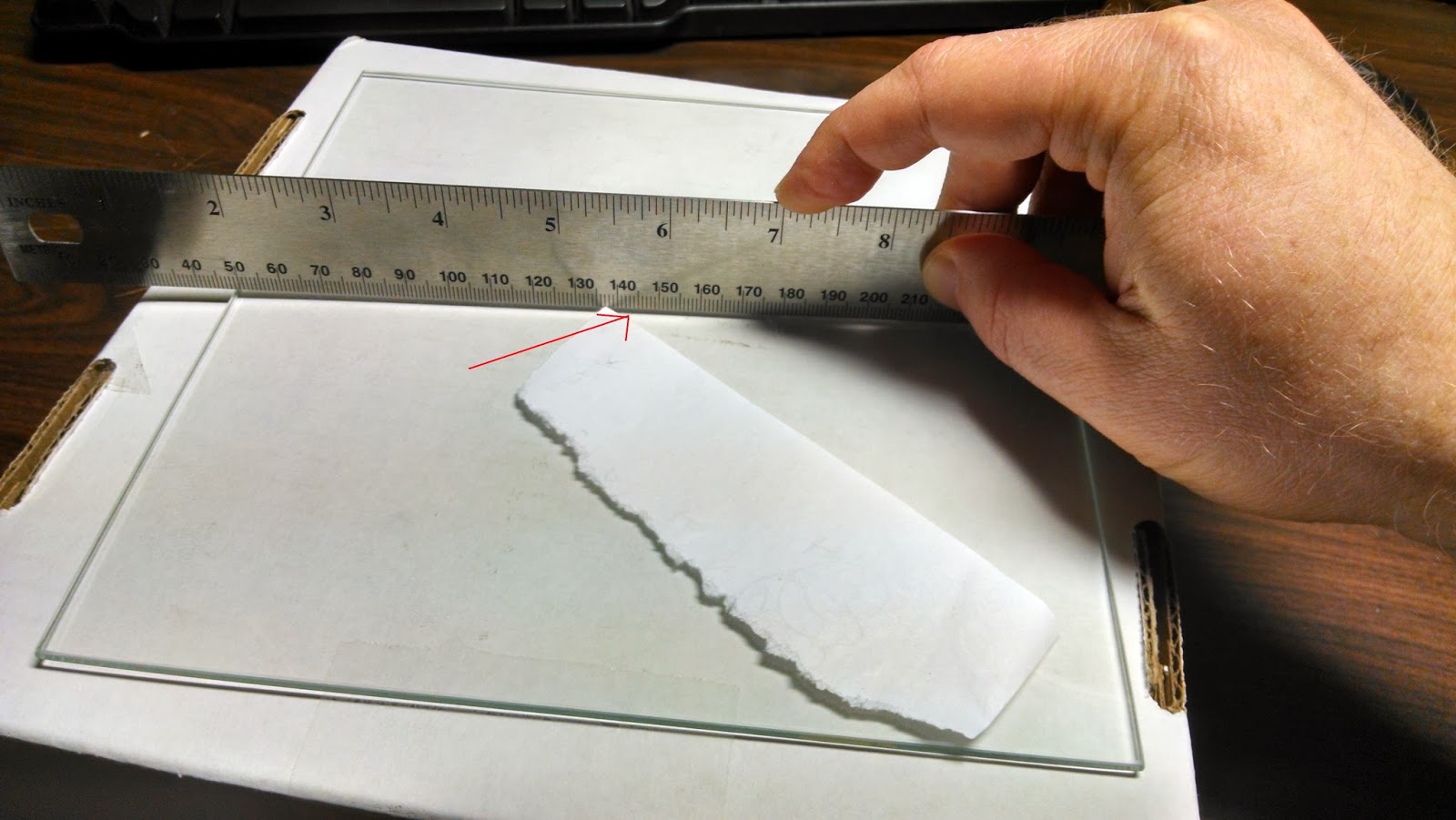 |
| Test for warped glass by sliding a scrap of paper between the ruler and the center of the glass |
|
So you're going to run 4 tests:
- Direction A at the edges
- Direction A in the center
- Direction B at the edges
- Direction B in the center
To be really sure, you should flip the glass over and trying these tests on the other side.
Mounting the Glass on The Heat Bed
Make sure that the glass has been attached to the heat bed using bulldog clips. It's important that the heat bed maintain contact with the glass throughout the entire surface to ensure that the glass's temperature is even.
I initially used the 4 bulldog clips that came with my kit. I was able to wedge a piece of paper between the heat bed and the glass, so I determined that the heat bed sagged in the middle a bit. So I added 4 more bulldog clips.
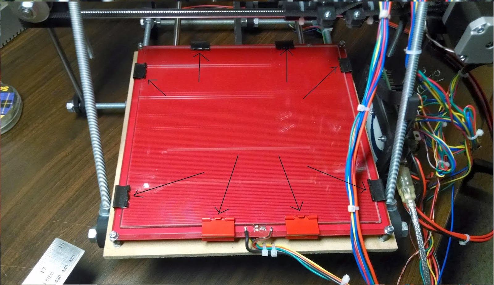 |
| Positioning the bulldog clips |
Z Axis Limit Switch and Heat Bed Calibration
You need a piece of scrap paper for this step.
Recall that
we installed the heat bed on springs. The height of the heat bed can be adjusted by turning the locknuts at each corner of the heat bed.
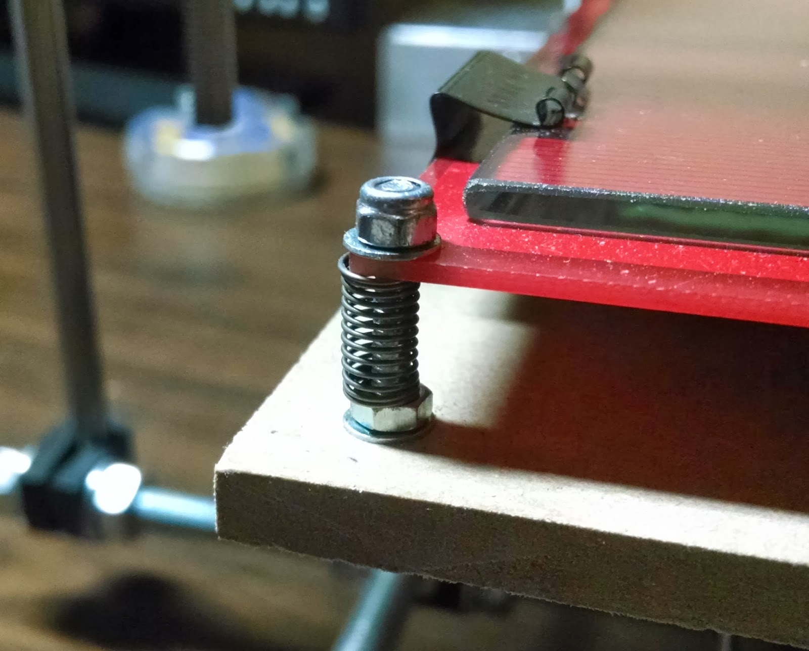 |
| One of the four corners of the heat bed with a locknut and spring on an M3 bolt. |
The idea here is to adjust the position of the Z axis limit switch and the height of each corner of the glass so that the Z axis limit switch clicks when the distance between the hot end nozzle and the glass is approximately the same as the thickness of a piece of paper.
From my experience this takes some of trial and error.
In my experience, the best way to achieve this is the following:
1. Lower the heat bed by turning the locknuts clockwise to compress the springs until maybe 1/8 inch of each M3 bolt is exposed at the top.
2. Position the heat bed so that the hot end is as close as possible to one of the corners.
3. Set the Z axis limit switch to some height where you think it will activate when the hot end is lowered within 1/8" of the glass. Tighten the two bolts on the Z axis limit switch. This step requires trial and error.
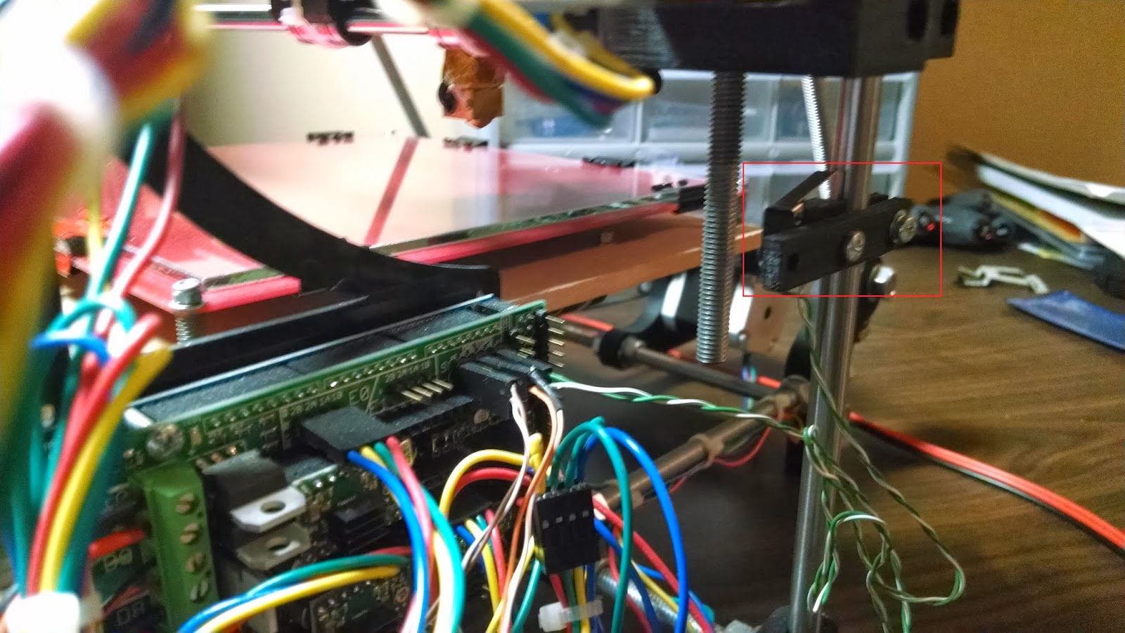 |
| Positioning the Z limit switch |
4. Use Pronterface to lower the hot end until the Z axis limit switch is activated.
5. If the hot end is less than 1/8 inch above the heat bed, proceed to step 6, otherwise go back to step 3.
6. Slowly turn the locknut counterclockwise to raise the heat bed. At regular intervals test the distance between the hot end and the glass by sliding a piece of paper between the hot end and the glass. When the paper starts to "grab" then stop.
7. Repeat for the other 3 corners - this means complete steps 2 and 6 for the other corners.
Making Sure The Glass Is Still Flat Upon Completion
Once you've adjusted the 4 corners of the heat bed, you can perform another test to determine if your glass is still perfectly flat, even after having been mounted on the heat bed. A flat piece of glass is necessary to ensure that your parts are printed consistently regardless of the placement on the glass. You'll need a piece of scrap paper for this step.
1. Use Pronterface to raise the hot end a couple mm.
2. Move the hot end to the center of the glass using Pronterface.
3. Use Pronterface to lower the hot end until the Z axis limit switch activates
4. Try to insert a piece of scrap paper between the hot end and the glass. If the glass is still perfectly flat, then the piece of paper should "grab" just a little between the hot end and the glass.
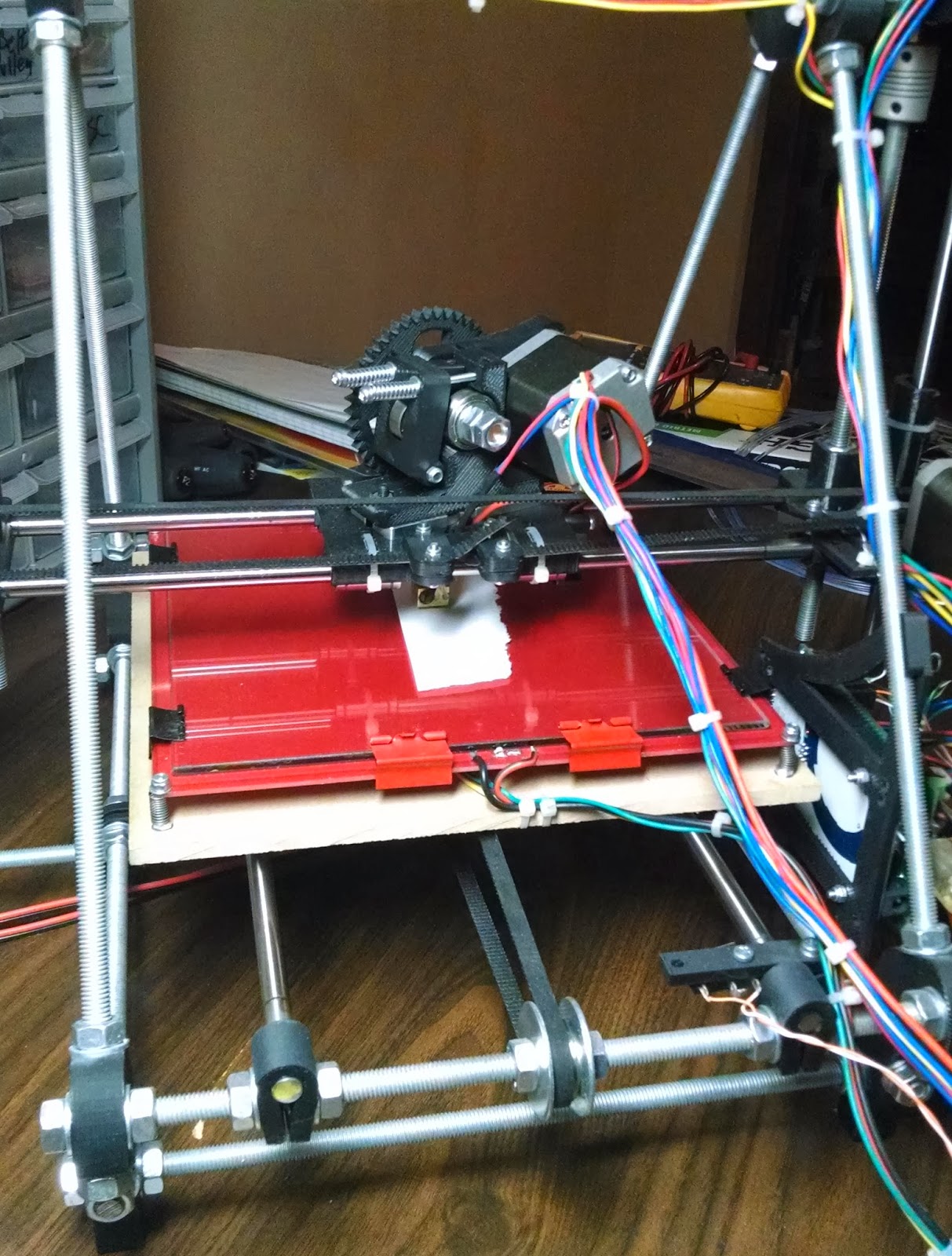 |
| Test for warped glass by sliding a scrap of paper between the hot end and the center of the glass after calibrating the height of the corners of the glass. |


.jpg)


.jpg)